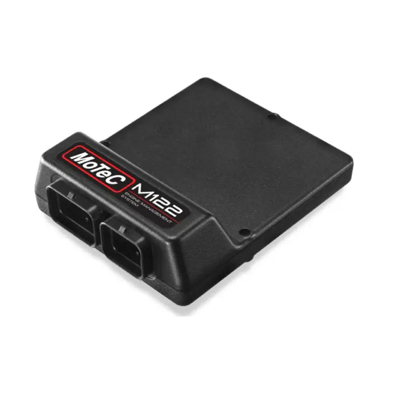
Injector
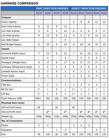
- Direct Injector Outputs: 4
- Low side Injector Outputs: 6
- Direct Injector Max Current (peak/hold) :20A/15A
- Direct Injector Max Voltage: 80V
Ignition
Auxiliary Outputs
Inputs
- Universal Digital: 7
- Digital: 0
- Analogue Voltage: 8
- Analogue Temperature: 4
- Knock: 2
- Lambda (narrow band): 0
Data
Wire Gauges
Battery
- Bat_Pos: All pins should be connected with AWG20, AWG18 or AWG16 wire to a switched battery supply.
- Bat_Neg: All pins should be connected with AWG20, AWG18, or AWG16 wire to a chassis ground or battery negative terminal. “Star” distribution should be employed to ensure that no ECU ground currents are mixed with actuator ground currents.
- Recommended minimum supply wiring: 1x BAT_POS, 2x BAT_NEG, AWG20
Outputs
Depending on the current draw for some outputs, a minimum wire gauge is recommended for safe operation.
- Low side ignition, Peak Hold Injector, Low Side Injector outputs: AWG20 (ideally) and AWG22 (optional).
- Direct Injectors:
- DI injector wiring should be as short as possible. Significant voltage losses occur if total wiring length exceeds 3m (both the + and – wires should be considered, so injectors should be wired less than 1.5 metres from the ECU where possible).
- Wire gauges AWG20 are preferred for Tyco connectors.
- Half bridge and Full bridge outputs: These outputs may be used to drive low side actuators, throttle servos and direct injection pumps. Wire size should be chosen to suit the current requirements of the actuator device. For example, throttle servos and direct injection pumps should use AWG18 or AWG20 wiring.
- Half bride or peak hold injector outputs provide internal recirculation circuitry whereas all low side outputs do not. In applications where camshaft solenoids and other inductive devices cannot be driven from outputs with internal recirculation circuitry, external recirculation by means of diode can be installed to prevent slow turn-off of some devices.
Physical
Dimensions: 162 x 127.5 x 40.5
Weight: 290g
Connectors:
- 1 x 34 pin Tyco
- 1 x 26 pin Tyco


